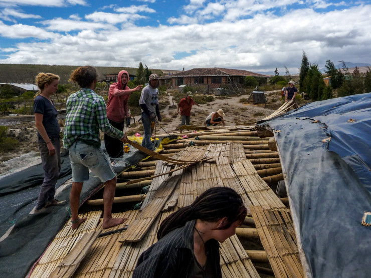
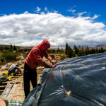
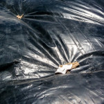
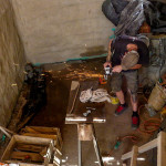
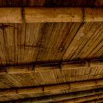
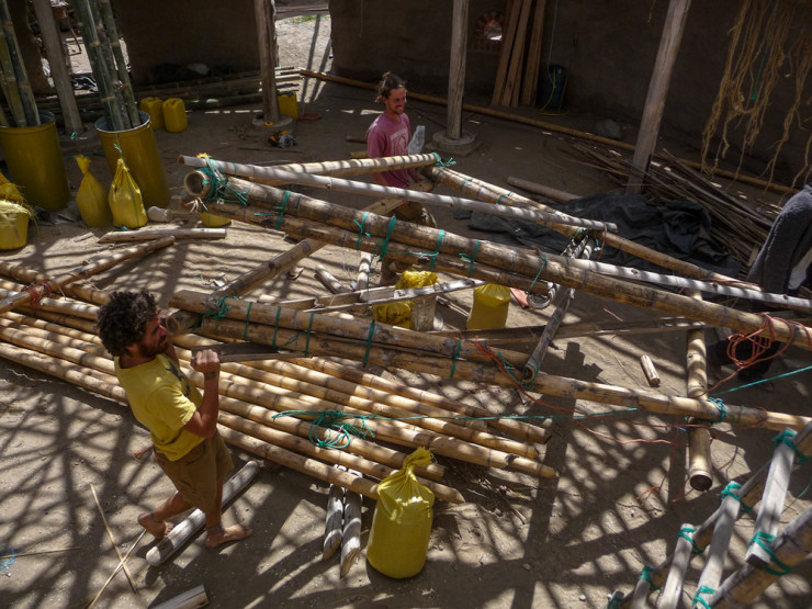
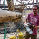
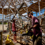
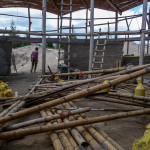
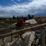
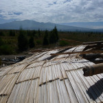
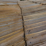
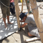
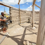
More of the same today, beams, cladding and ferrocement later in the afternoon. We also started stapling plastic onto the reciprocal roof. Some of the cladding on the arches had quite large gaps, meaning that the red bag material we had been using would have been visible from beneath, so we used black plastic instead.
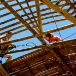
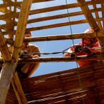
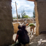
We invited Architect Juan Alfonso Peña to visit the site one day. He’s been building natural homes for quite some time and had lots of advice regarding the stability of our structure. He made a few recommendations, one was to include more beams in the balcony, another was to include some diagonal supports, and another was some tension cable.
The diagonal supports, or Trusses, have always been part of the design. With the structure of the building exposed it will be easy to add these later as their main function is support in high winds and earthquakes, preventing lateral movement.
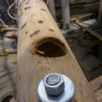
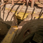
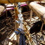
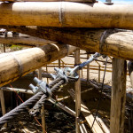
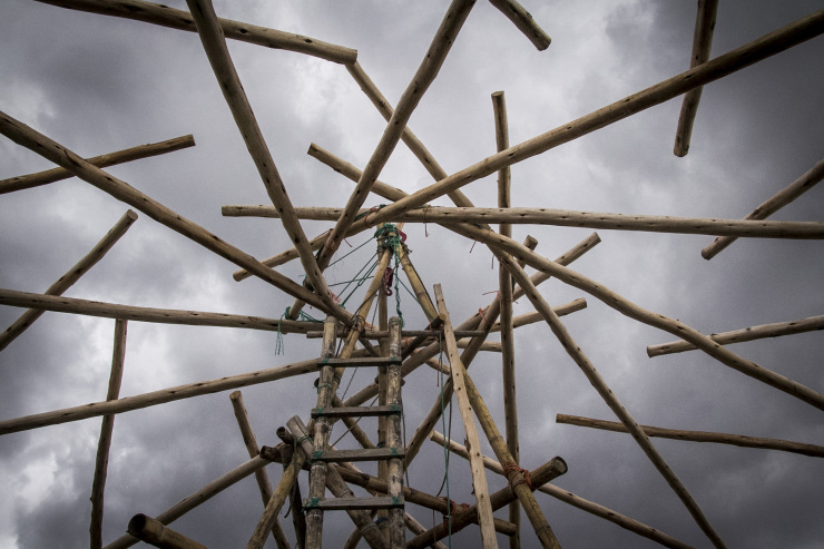
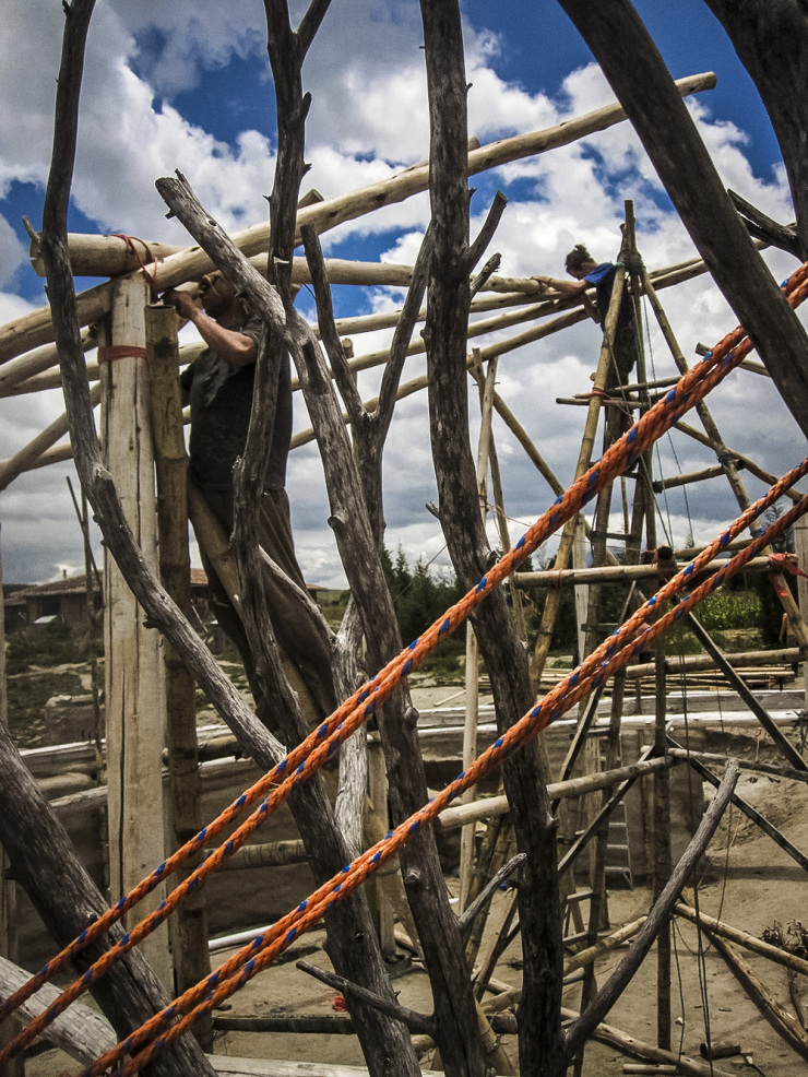
The tension cable however is something we did right away. My understanding is that reciprocal roofs only create downwards force, rather than pushing laterally on the columns. But if anything was going to move, it would most likely be that the columns would be forced outwards or that the connections with the beams would break. For this reason we installed two tension cables. One circle through holes in the ends of the beams, and one circle through holes in the tops of the columns. With two 1/2″ tension cables there is no way the circle can get any bigger.
We also wrapped galvanised steel wire around the beams and columns on either side of the cable to prevent the cable from splitting the wood. Finally we added a cable clamp on either side of the beam (or column) to stop it from sliding along the cable.
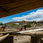
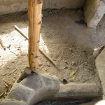
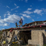
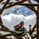
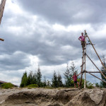
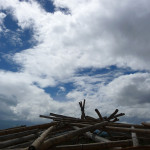
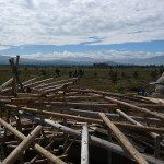
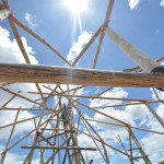
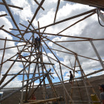
It’s been a long time coming, but its time to take down the tripod. Not only did we use it to raise the 12 main columns, we also used it to position all the roof beams, climb up to the roof and lift materials to the roof. We had a lot of fun climbing up and down this structure over the past 6 months, pretending to be monkeys.
The length of the legs and bottom supports were designed so that we could just cut them off, fold it up and slot it out of the door. It almost fit, we only had to dig a tiny hole.
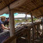
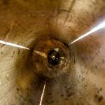
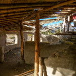
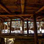
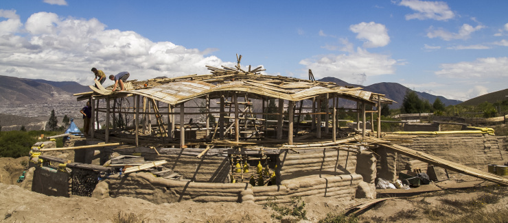
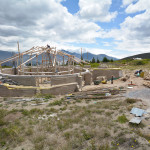
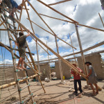
For the first time the hall is empty, its pretty big in there!
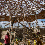
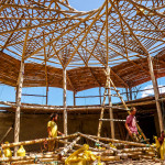
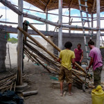
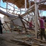
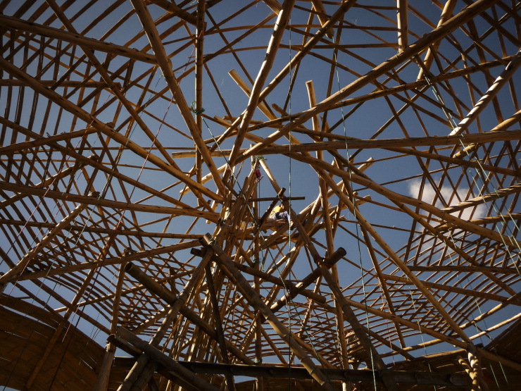
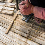
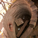
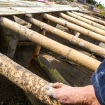
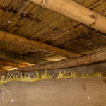
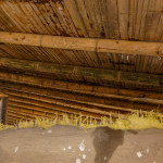
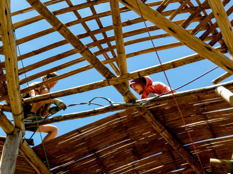
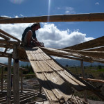
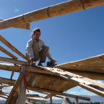
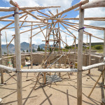
Split/ open bamboo (guadua) was bent over the bamboo beams onto the eucalyptus beams to create 12 shallow barrel arches. Next we’ll be putting a layer of ferro-cement and light weight pumice concrete, so the arch shape ensures the concrete is in a compressive shape. Although the arches are far too shallow to function independently of the underlying structure, the shape is still desirable over a flat span.
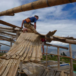
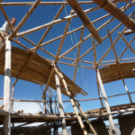
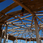
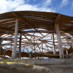
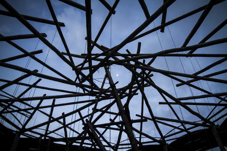
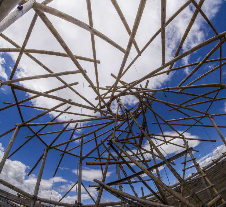
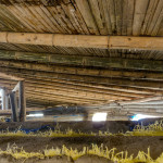
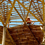
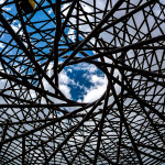
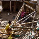
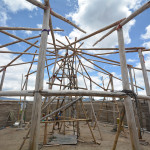
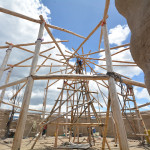
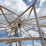
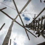
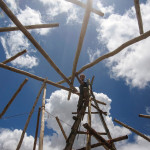
To fill the large spaces between the Eucalyptus beams, we built another double reciprocal roof offset from the first using bamboo. This was easy as we already had the shape, pitch, and support of the wooden beams below. The bamboo beams are not yet connected to the wood, only to themselves. We will put in columns next, to the concrete bond beam, to raise the bamboo structure slightly and then we’ll weight down the bamboo to touch the eucalyptus. With the Bamboo structure slightly higher than the Eucalyptus structure, the cladding will create 12 shallow barrel arches, it should look a bit like a circus tent, or a hot air balloon, or a shell, we hope.
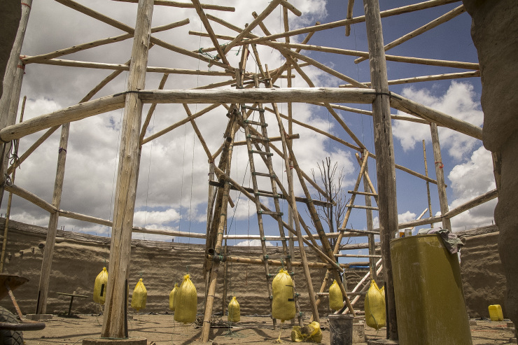
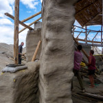
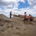
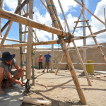
We hung 50kg earthbags from the tips of each of the outer reciprocal beams for a few reasons.
Firstly it raised up the back end of outer reciprocal beams, which are connected to the columns with a joint that allows them the see-saw, thus lowering the tips onto the inner reciprocal beams to create the double reciprocal structure. This allows us to put in 12 outer columns from the bottoms of the beams down the the concrete bond beam.
Next, it pre-stresses the structure. We plan to use ferro-cement to cover the roof but the weight of the mortar will compress the structure during application, so we are pre-stressing to achieve the final shape and removing the weights as we lift the mortar.
Finally, it is the first step in testing the strength of the roof. More weights will be added later.
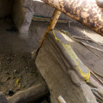
We connected the tips of the outer beams with the inner beams using two 7″ nails in each connection, they will also be tied with thick wire.
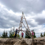
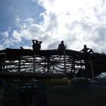
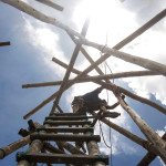
With extra supports on beams 1, 5 and 9, removing the Charlie stick was as easy as opening the legs to lower it down. The next 2 hours involved a process of lowering one support at a time to slowly lower the first reciprocal beam onto the last so that they all support each other. On beam one we had a car jack which could be lowered easily. Supports 5 and 9 required a little extra love, which involved digging an inch deep hole next to the base and kicking it in so that the other two supports took up the slack. This worked well, at all times 2 of the supports were taking the weight of the beams, so we worked around each one, lowering them a bit at a time until the first beam sat in the notch of the final beam. Then, with a little more lowering all three supports came free and the roof is reciprocally supported.
We then used one of the supports and the jack to raise the beams where necessary, allowing us to twist and reposition each beam slightly, using the level lines that were drawn on the tips during preparations to get all the notches in the right places.
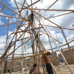
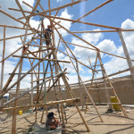
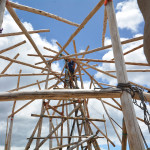
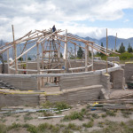
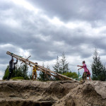
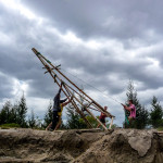
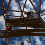
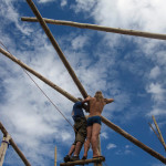
Raising the Inner Reciprocal beams took two days, it was a process of lifting the back end using a rope over the top of a column, and the tip using a pulley on the tripod. The first beam was held in place by a ‘Charlie’ stick, two poles connected at the top to create an A-frame, that can be closed or opened to raise point of the first beam. Positioning it was surprisingly quick, we got lucky. Line 3 (see previous post) on the tip of the beam had to be directly over the circle drawn on the floor, 636.6cm high… approximately. This was the height of the columns (5m) plus the pitch of the roof (106.6cm) plus a little extra (30cm) so that the final beam had space to slot under the first before we lowered the charlie stick.
We also placed support poles on beams 5, 9 and next to the charlie on beam 1 so that the charlie stick wasn’t taking all the weight and so that we could lower each a bit at a time to settle the roof.
© 2026 Another Bag in the Wall | Theme by Eleven Themes