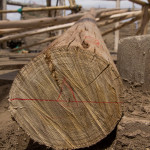
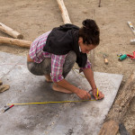
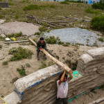
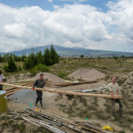
We simulated the position of the inner reciprocal beams on the ground before raising them. The usual procedure is to approximately notch where the beams will overlap and then hope that they settle into place once raised. Instead we positioned them exactly as they would be so we could cut the correct angle on the notch. Using a metal sheet as a level, we marked a 1.5m circle which will be the size of the central sky light. We then placed 4 marks on each beam, which were determined using cad software.
1. 30 cm from the bottom – where the beam will sit on the column.
2. 487.5 cm from line 1 – where the notch will be cut
3. 40 cm from line 2 – where the beam sits in the notch of the next beam along
4. 40 cm from line 3 where we will cut the beam off later (we are leaving them long for now, its not much extra weight and it will help with lifting them
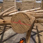
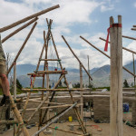
We then placed the base of beam 1 by the base of column 1, and using a plumb line we aligned lines 2 & 3 over the skylight circle. A temporary ‘charlie’ stick of 106.6cm was placed under line 3 to simulate the roof pitch.
Next we cut a notch at line 2 and placed the second beam in the notch, adjusting as necessary until line 3 of this beam was 106.6cm over the metal sheet, again using a plumb line. Finally we marked a level line on the base and tip of each beam so we could get the notch on top easily when reassembling. We continued around the circle in this manner until we were at beam 9, when we took it all down repeat the process from the beginning for the final three beams. With the roof in its final position it would be impossible to slot in the final beam, hence dismantling the first 9. When we raise the roof the charlie stick will be 30cm higher than necessary to leave a gap over beam 11 through which beam 12 can slot, under beam 1; more on this later.
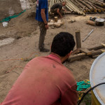
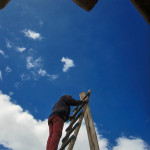
In the other photos you can see our 6m long drill bit, a standard 1/2″ bit welded onto 6m or rebar, which we’re using to drill holes through the bamboo so we can pour in borax solution to preserve them. You can also see our new rope harness being tested, thanks James.
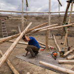
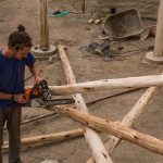
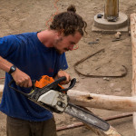
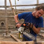
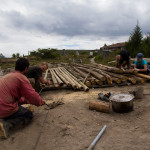

We laid out the inner reciprocal beams on the floor first and simulated their position in order to cut out grooves in the right places, safely. More photos are on their way.
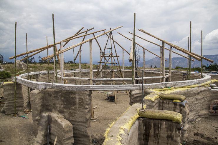
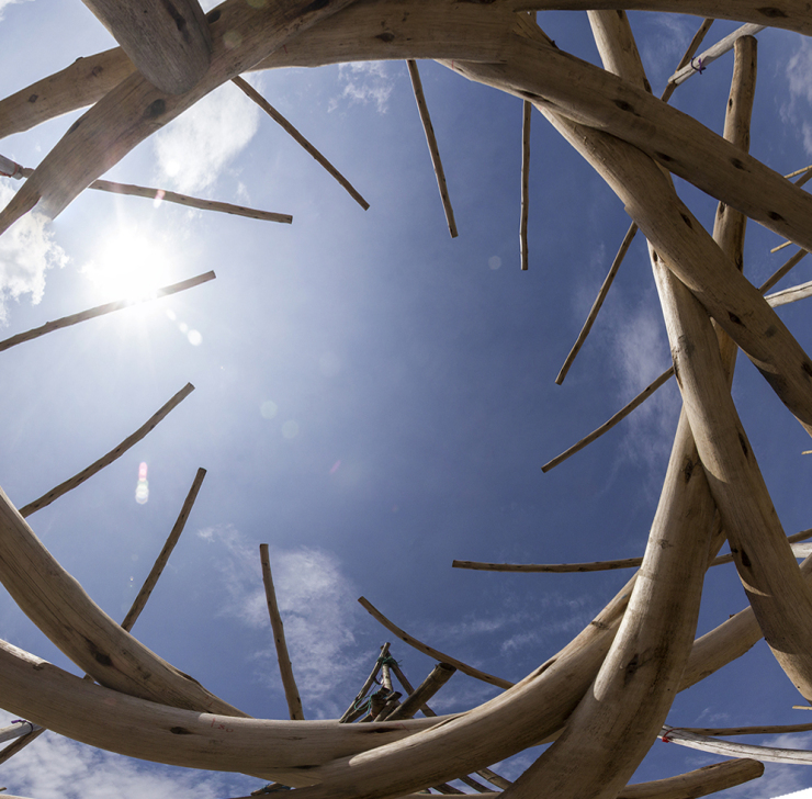
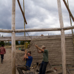
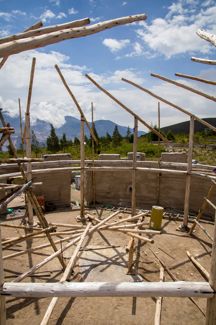
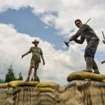
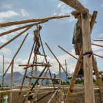
We’re going to make a double reciprocal roof, like this one (wikipedia) but with extra columns supporting the inner reciprocal beams. This way if any element fails the weight can be taken by a neighboring column until things can be fixed.
In order to do this we raised the outer beams first, using a joint that allows the ends to move up and down (like a seesaw). The back end is held in place temporarily with bamboo whilst we raise the inner reciprocal beams. Columns will be added later down to the concrete bond beam instead of the bamboo, but we don’t know their length until the whole thing is built so they’ll have to wait.


© 2026 Another Bag in the Wall | Theme by Eleven Themes