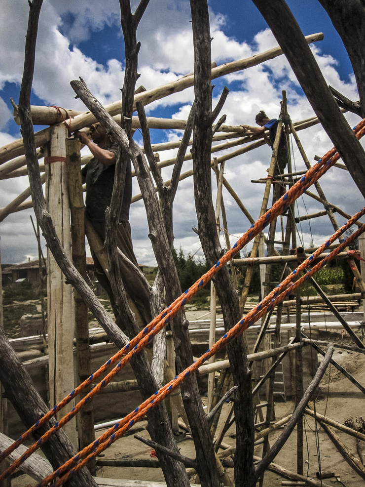
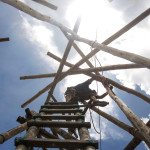
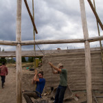
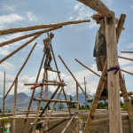
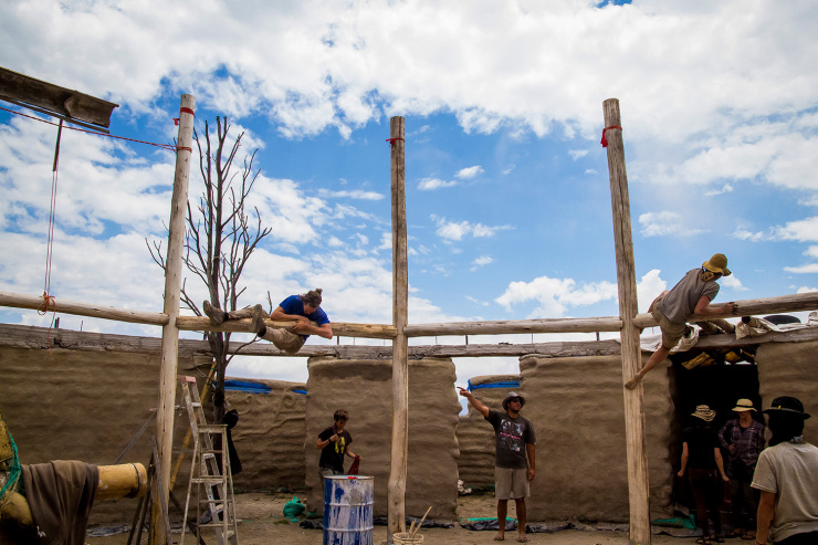
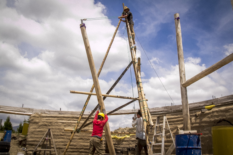
Raising the Inner Reciprocal beams took two days, it was a process of lifting the back end using a rope over the top of a column, and the tip using a pulley on the tripod. The first beam was held in place by a ‘Charlie’ stick, two poles connected at the top to create an A-frame, that can be closed or opened to raise point of the first beam. Positioning it was surprisingly quick, we got lucky. Line 3 (see previous post) on the tip of the beam had to be directly over the circle drawn on the floor, 636.6cm high… approximately. This was the height of the columns (5m) plus the pitch of the roof (106.6cm) plus a little extra (30cm) so that the final beam had space to slot under the first before we lowered the charlie stick.
We also placed support poles on beams 5, 9 and next to the charlie on beam 1 so that the charlie stick wasn’t taking all the weight and so that we could lower each a bit at a time to settle the roof.
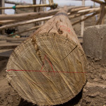
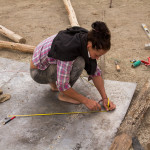
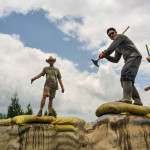
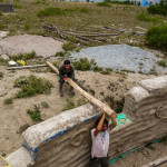
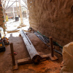
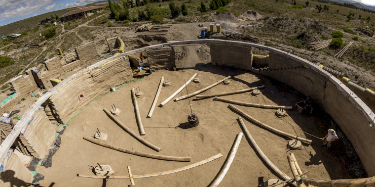
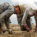
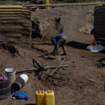
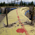
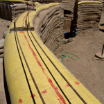
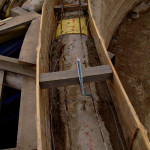
We simulated the position of the inner reciprocal beams on the ground before raising them. The usual procedure is to approximately notch where the beams will overlap and then hope that they settle into place once raised. Instead we positioned them exactly as they would be so we could cut the correct angle on the notch. Using a metal sheet as a level, we marked a 1.5m circle which will be the size of the central sky light. We then placed 4 marks on each beam, which were determined using cad software.
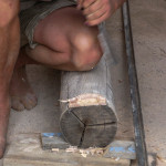
1. 30 cm from the bottom – where the beam will sit on the column.
2. 487.5 cm from line 1 – where the notch will be cut
3. 40 cm from line 2 – where the beam sits in the notch of the next beam along
4. 40 cm from line 3 where we will cut the beam off later (we are leaving them long for now, its not much extra weight and it will help with lifting them
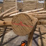
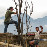
We then placed the base of beam 1 by the base of column 1, and using a plumb line we aligned lines 2 & 3 over the skylight circle. A temporary ‘charlie’ stick of 106.6cm was placed under line 3 to simulate the roof pitch.
Next we cut a notch at line 2 and placed the second beam in the notch, adjusting as necessary until line 3 of this beam was 106.6cm over the metal sheet, again using a plumb line. Finally we marked a level line on the base and tip of each beam so we could get the notch on top easily when reassembling. We continued around the circle in this manner until we were at beam 9, when we took it all down repeat the process from the beginning for the final three beams. With the roof in its final position it would be impossible to slot in the final beam, hence dismantling the first 9. When we raise the roof the charlie stick will be 30cm higher than necessary to leave a gap over beam 11 through which beam 12 can slot, under beam 1; more on this later.
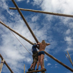
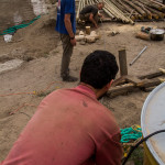
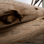
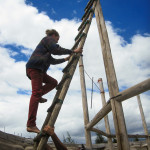
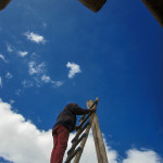
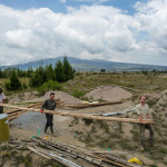
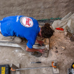
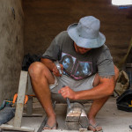
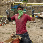
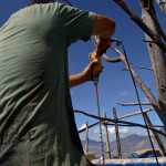
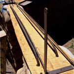
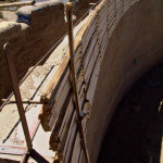
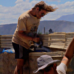
In the other photos you can see our 6m long drill bit, a standard 1/2″ bit welded onto 6m or rebar, which we’re using to drill holes through the bamboo so we can pour in borax solution to preserve them. You can also see our new rope harness being tested, thanks James.
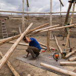
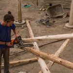
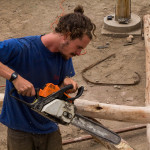
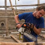
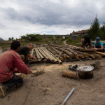
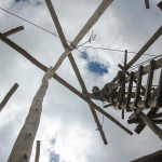
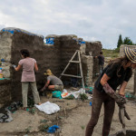
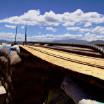
We laid out the inner reciprocal beams on the floor first and simulated their position in order to cut out grooves in the right places, safely. More photos are on their way.
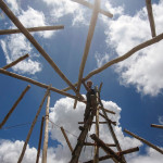
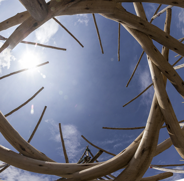
We’re going to make a double reciprocal roof, like this one (wikipedia) but with extra columns supporting the inner reciprocal beams. This way if any element fails the weight can be taken by a neighboring column until things can be fixed.
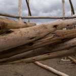
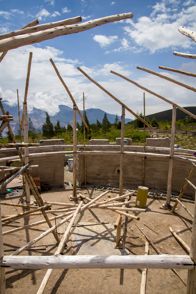
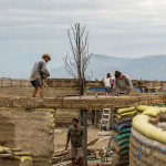
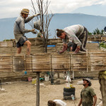
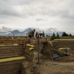
In order to do this we raised the outer beams first, using a joint that allows the ends to move up and down (like a seesaw). The back end is held in place temporarily with bamboo whilst we raise the inner reciprocal beams. Columns will be added later down to the concrete bond beam instead of the bamboo, but we don’t know their length until the whole thing is built so they’ll have to wait.
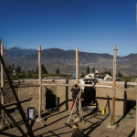
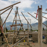


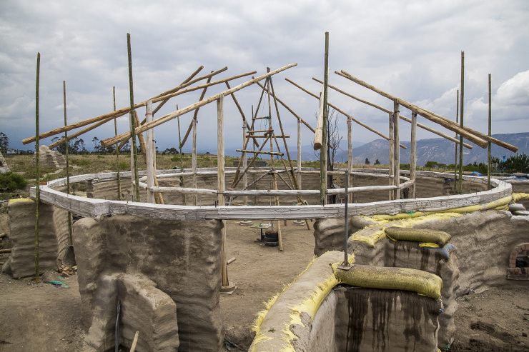
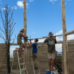
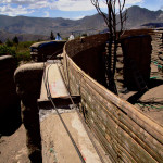
Between the concrete bond beam and the 12 columns will be a bamboo balcony, an area with hammocks, bookshelves and a long clothes rack for the free shop. The stairs on the east side of the hall will lead around the balcony to the lounge, where we’ll have another staircase near the front door. We measured, cut and placed the beams as we rose each column, and with the final beam in place a constant ring of beams prevents any movement, so its now a giant climbing frame.
Metal brackets will be screwed in next hold to it all together, and trusses will be added later for extra strength in the event of an earthquake.
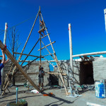
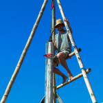
We built a 7m high bamboo tripod and used a multiplier pulley to raise our columns, here’s a photo of the third going up. This made the process so easy that we could raise the column, level vertically with a plumb line, scribe a level line at the base using the concrete pedestal as a guide, and lower it again to chainsaw the bottom level. We also put a thin concrete latex slurry under each column, this was concrete with a PVA additive to create a waterproof membrane, preventing wicking and rising damp, whilst also reducing cracking.
The 2 flat steel bars protruding from the concrete were strong enough to hold the column in place whilst we moved the tripod and fitted the first beam, more on beams later.
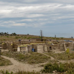
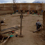
The bond beam with the bamboo form removed. The columns are laid out ready to be raised and we have built a bamboo tripod to lift them.
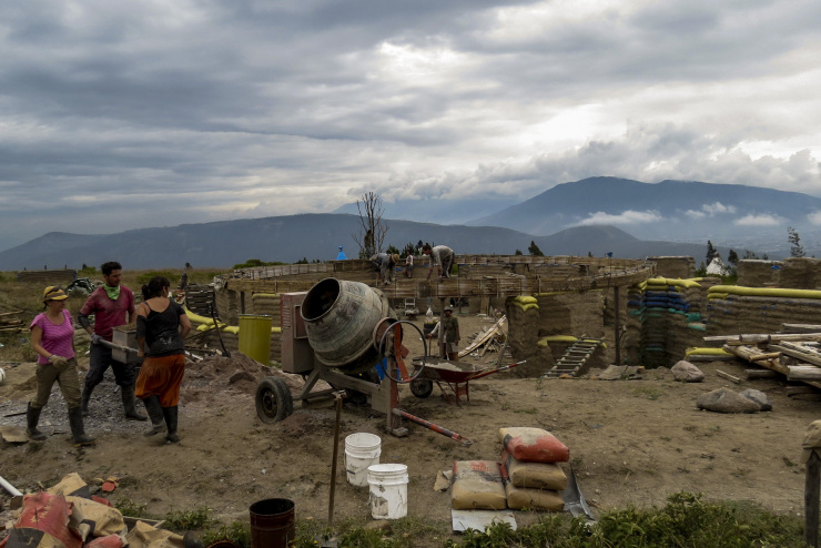
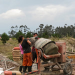
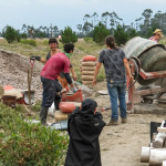
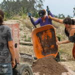
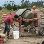
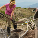
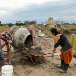
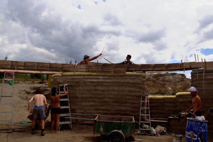
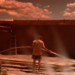
The whole community came down to site for a full day of concrete mixing, and we were lucky enough to have clouds for once. It was very well disorganized but everybody found something to do. we started with two groups of 2 on ladders at one side of the circle (we only have 4 ladders) and went in opposite directions around the circle until we met up again 8 hours later. The bamboo box held up very well, and although it was tedious to build, the fact that it wasn’t rigid meant that we could shake, tap and vibrate it to help tamp the concrete easily.
We even had time at the end of the day to lay a concrete sub floor in the storage room, which will come in very handy later when leveling, marking and cutting the wooden beams. We rushed a little but its more or less level (it was dark when we finished).

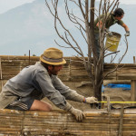


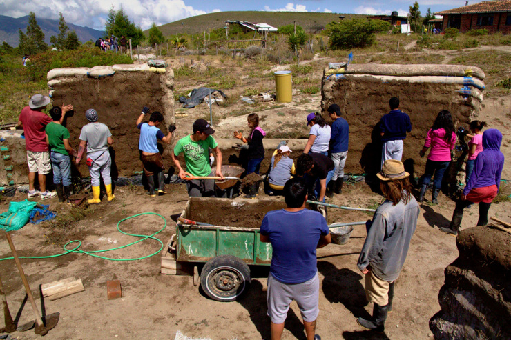
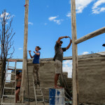
We’ve been working with a local foundation who bring kids out of the city for some farming fun, they enjoy having mud fights and we’re happy to see the next layer of plaster nearly finished.
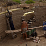
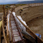
Building codes state that before we go any higher with the walls we must create a continuous bond beam or ring beam to tie all the walls together. Although there are many ways to achieve this, with wood or filling earthbags with concrete, etc, we decided to go with the conventional technique, a cast-in-situ constant concrete beam. Although its perhaps not as environmentally friendly as a wooden bond beam, we decided that a poured concrete beam would be cheaper, which might not have been the case in hindsight. With this method the bond beam also doubled up as lintels over the doors, and allowed us to mount J-bolts and flat iron connection points for the post and beam structure above.
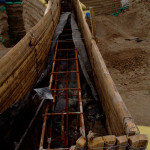
We made the form out of split bamboo, the cheap option, but found that we had to connect countless vertical bamboo supports with seemingly thousands of pieces of wire in order to hold it all together; needless to say it took longer than expected. The height of the beam varied in order to use the least possible concrete whilst still having strength over the openings; we made the beam 15cm over the walls and small openings (1m), 20cm over the larger openings (2m) and 30cm over the largest opening (3.6m) with extra reinforcement bars in the small openings and rebar cages in the larger openings. Luckily during the design process we had a chance hitch-hiking encounter with a civil engineer and after half an hour of chatting and fag packet sketches he assured us that we had successfully over engineered our bond beam.
The Earthbag Building Book recommended hammering rebar nails down into the earthbags whilst they were still fresh, but some havn’t been fresh for months now, so to avoid cracking the earth we drilled deep holes, poured in a concrete and pushed in the bars, this seemed to work well and we spaced them every 50cm on a slight angle, going 30cm deep into the bags.
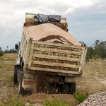
Time to bring in the mixer.


© 2026 Another Bag in the Wall | Theme by Eleven Themes